In modern drone systems, the Inertial Measurement Unit (IMU) is one of the most critical components. It directly affects flight stability, control accuracy, and overall reliability. While many beginners focus on motors, ESCs, or flight controllers, experienced engineers know that poor IMU selection can make even the best hardware perform poorly.
This article provides a practical, engineering-focused guide to selecting the right IMU for production-grade drones.
Why IMU Selection Matters
An IMU provides real-time data about angular velocity and acceleration. This data is used by the flight controller to:
Stabilize the drone
Execute PID control loops
Handle disturbances like wind and vibration
If the IMU data is noisy or unstable, the entire control system suffers.
Key Parameters for IMU Selection
Gyroscope Noise Density (Most Important)
Gyroscope noise density determines how much random noise is present in angular velocity measurements.
For high-performance drones, this is the single most important parameter.
Sampling Rate (ODR – Output Data Rate)
The sampling rate determines how frequently the IMU updates data.
Higher ODR allows faster response to disturbances
Enables better filtering and control loop performance
Typical values:
Entry-level: ~1 kHz
Flight controller loops: typically 2–10 kHz
Advanced IMUs: up to 32 kHz (provides headroom rather than a strict requirement)
While 32 kHz is supported by high-end IMUs, most practical drone control loops operate at lower frequencies due to processing and system constraints.
Drift and Bias Stability
Drift refers to the gradual accumulation of error over time.
Critical for long-duration flights
Essential for autonomous and mapping drones
Note: Datasheets often provide limited real-world drift data. Practical performance depends heavily on calibration and temperature compensation.
Interface (SPI vs I2C)
For drones, SPI is strongly recommended.
SPI provides deterministic timing and higher bandwidth
I2C introduces latency and potential instability
Production drones should always prefer SPI-based IMUs.
Vibration Handling and Filtering
Drone motors generate significant vibration, which directly affects IMU readings.
Important features:
Digital Low Pass Filters (DLPF)
Anti-aliasing filters (AAF)
Even with good filters, mechanical damping is essential.
Power Consumption
While not critical for all drones, power efficiency matters in battery-sensitive applications.
Low-power IMUs are suitable for IoT and wearable systems
Performance-oriented IMUs consume more power but deliver better results
Comparative Analysis of Popular IMUs
High-Performance Category
Example: ICM-42688-P
Very low gyro noise (~2.8 mdps/√Hz)
High sampling rate (up to 32 kHz)
High-speed SPI support
Use case:
FPV drones
Racing drones
Production-grade flight controllers
Mid-Range Category
Example: BMI270
Moderate gyro noise (~8 mdps/√Hz)
Lower power consumption
Balanced performance
Use case:
Budget drones
General robotics
Industrial / Embedded Category
Examples: LSM6DSL / LSM6DSO
Moderate noise (~5 mdps/√Hz)
Good stability and reliability
Widely used in embedded systems
Use case:
Industrial robotics
Embedded and IoT systems
Entry-Level (Hobby)
Example: MPU-6050
High noise
Higher drift
Limited performance
Use case:
Learning
Prototyping
Not recommended for production drones
Real-World Engineering Considerations
Selecting the right IMU is only part of the solution. System-level design plays a critical role.
1. PCB Layout
Keep IMU away from high-noise components
Proper grounding and decoupling are essential
2. Power Supply Filtering
Use clean and stable power rails
Add proper capacitors near the IMU
3. SPI Bus Design
Avoid sharing SPI with noisy peripherals
Maintain signal integrity at high speeds
4. Mechanical Mounting
Use vibration damping materials
Avoid rigid mounting directly on high-vibration frames
Common Mistakes
Choosing IMU based only on price
Ignoring noise density
Using I2C in high-performance systems
Poor PCB layout and grounding
No vibration isolation
Final Recommendation
For most production drones:
Choose an IMU with low gyro noise density
Prefer high sampling rates
Always use SPI interface
Focus on system-level design
A high-performance IMU combined with proper hardware design ensures stable, reliable, and efficient drone operation. and embedded engineering solutions.
Conclusion
IMU selection is not just about specifications. It is about understanding how sensor characteristics interact with control systems, mechanical design, and real-world conditions.
In production drones, performance is determined not only by the IMU itself, but by how well the entire system is engineered.
Vihaan IoT Gateway Delivering practical IoT and embedded engineering solutions.
Amazon Cognito serves as a robust identity platform for web and mobile applications, functioning as a user directory, authentication server, and OAuth 2.0 authorization service for access tokens and AWS credentials.
It enables seamless authentication and authorization from built-in directories, enterprise systems, or consumer providers like Google and Facebook.
Cognito provides two powerful components:
User Pools
Identity Pools
Although they sound similar, they solve two completely different problems.
Cognito Identity Pools
Amazon Cognito Identity provides temporary AWS credentials to mobile or web applications. These credentials automatically expire and are restricted using IAM policies, allowing apps to securely access services such as AWS IoT Core, S3, and DynamoDB without exposing long-term secrets.
Identity Pools support:
Authenticated users
Unauthenticated (guest) users
In simple words: Identity Pools answer the question — “What can you do in AWS?”
How to Create an Amazon Cognito Identity Pool (Federated Identity)
I have recorded a detailed step-by-step tutorial explaining how to create an Identity Pool in Amazon Cognito. You can watch the full walkthrough here:
User Pools
Amazon Cognito User Pool is a managed user directory that handles authentication for your application.
It allows you to:
Register (Sign Up) users
Authenticate (Sign In) users
Manage passwords
Store user attributes (email, phone, etc.)
After successful authentication, a User Pool issues JWT tokens:
ID Token (contains user identity information)
Access Token (used to authorize API access)
Refresh Token (used to obtain new tokens)
Supported Login Methods
Username & Password
Social providers (Google, Facebook, etc.)
SAML / OIDC identity providers
In simple words: User Pools answer the question — “Who are you?”
Key Differences
Feature
User Pools
Identity Pools
Main Purpose
Authentication
Authorization
Output
JWT Tokens
Temporary AWS Credentials
Manages Users?
Yes
No
Grants AWS Access?
No
Yes
How They Work Together (Temporary Credentials Flow)
This pattern is very common in mobile and IoT applications.
Step 1: User Logs In
User authenticates via User Pool and receives JWT tokens.
Step 2: Get Identity ID
The app sends the token to the Identity Pool (GetId API) and receives a Cognito Identity ID.
Step 3: Exchange for Temporary Credentials
The app calls GetCredentialsForIdentity to obtain temporary AWS credentials.
Step 4: Access AWS Services
The app uses those credentials to securely access services like:
Amazon S3
Amazon DynamoDB
AWS IoT Core
All without embedding long-term AWS access keys in the application.
IoT Use Case Example
In IoT applications:
A mobile app authenticates the user via User Pool.
Identity Pool provides temporary AWS credentials.
Those credentials are used to securely connect to AWS IoT Core over WebSocket (MQTT over WSS) using SigV4 authentication.
AWS IoT policies control which devices (“Things”) the user can publish or subscribe to.
This allows secure, scalable, fine-grained device access control.
Final Summary
User Pools = Authentication (Who are you?)
Identity Pools = Authorization (What can you do?)
Together, they provide secure and scalable access control for mobile, web, and IoT applications.
If you’re building IoT systems, mobile apps, or serverless architectures on AWS, understanding this difference is essential.
References:
Amazon Cognito Developer Guide – Official AWS Documentation
Disclaimer: This article is an independent review and summary of publicly available information. Arduino®, Qualcomm®, and other product names are trademarks of their respective owners. All specifications are sourced from official product pages and announcements.
Introduction
In October 2025, Qualcomm Technologies announced its acquisition of Arduino, a pioneer in open‑source electronics and maker boards. Shortly after, Arduino unveiled the Arduino UNO Q, a hybrid “dual-brain” development board that merges powerful computing and real‑time control in the familiar UNO form factor.
This opens exciting possibilities for makers, IoT developers, educators, and robotics enthusiasts around the world.
What is Arduino UNO Q?
The Arduino UNO Q is more than just another Arduino board — it’s a hybrid platform built for modern IoT and AI applications. Designed as the ultimate learning companion, the UNO Q is simple enough for beginners yet powerful enough for advanced creators. From blinking your first LED to building intelligent IoT and AI systems, it empowers innovation at every stage of your journey.
The UNO Q is also the first Arduino board to work seamlessly with Arduino App Lab, a versatile integrated development environment that supports both Python and Arduino Sketch for easy programming of its unique “dual-brain” architecture.
Dual‑Brain Architecture: Linux Power Meets Real‑Time Precision
At its core, the Arduino UNO Q features a dual‑processor design:
A Linux® Debian–capable microprocessor powered by the Qualcomm Dragonwing™ QRB2210, delivering quad‑core performance, AI and graphics acceleration, and full camera, audio, and display support.
A real‑time STM32U585 microcontroller, ensuring precise control, instant responsiveness, and reliable execution for time‑critical tasks.
This combination allows one processor to handle “smart” functions — like AI, connectivity, and data processing — while the other ensures flawless real‑time control of sensors, motors, and other peripherals.
Multimedia: Camera, audio I/O, RGB LEDs, LED matrix display
OS: Debian Linux on MPU, Arduino Core + Zephyr OS on MCU
Why Qualcomm Buying Arduino Is a Big Deal for Tech Beginners
Arduino has long been a favorite among hobbyists, educators, and makers for its open‑source nature and ease of use. Qualcomm’s acquisition brings the power of advanced AI, connectivity, and processor technology to the Arduino ecosystem, enabling projects that are smarter, faster, and more capable than ever before.
For learners, this means access to cutting‑edge tools without sacrificing the simplicity that makes Arduino special. For makers and developers, it opens a new era of intelligent IoT and robotics innovation.
Wrapping Up
Qualcomm’s acquisition of Arduino marks a significant milestone for the maker community. The Arduino UNO Q represents the first step toward merging simplicity with advanced processing power, empowering hobbyists, educators, and innovators to create the next generation of connected devices.
At Vihaan IoT Gateway (VIG), we’re excited to follow this journey. We’ll continue to share updates, tutorials, and resources to help you get the most out of this new era of Arduino innovation.
🔗 Explore Arduino boards and accessories now: Vihaan IoT Gateway Arduino Store
References
Note: For security compliance, the following URLs are provided as plain text and are not clickable. Please copy and paste them into your browser to visit the respective pages.
Arduino official announcement on joining Qualcomm Technologies: www.arduino.cc/qualcomm
Qualcomm official press release on acquiring Arduino: www.qualcomm.com/news/releases/2025/10/qualcomm-to-acquire-arduino-accelerating-developers--access-to-i
Forbes article on Qualcomm acquiring Arduino and embedded platform strategy: www.forbes.com/sites/moorinsights/2025/10/07/qualcomm-acquires-arduino-to-advance-its-embedded-platform-strategy/
CNBC coverage of Qualcomm acquiring Arduino and the launch of Arduino UNO Q: www.cnbc.com/2025/10/07/qualcomm-acquires-italian-hardware-company-arduino-in-robotics-play-.html
PCMag report on Qualcomm buying Arduino and AI tools for DIY projects: www.pcmag.com/news/qualcomm-buys-arduino-will-bring-ai-tools-to-your-diy-tech-projects
Arduino official product page for Arduino UNO Q specifications: www.arduino.cc/product-uno-q
In our previous blog, we demonstrated how to set up an AWS IoT Core account and control a relay using an ESP32. That project was a great starting point for cloud-connected home automation.
In this tutorial, we will take it a step further by integrating an MQ-2 gas sensor with the ESP32 to detect harmful gases like LPG, methane, and smoke. The ESP32 will send these readings to AWS IoT Core, and our custom mobile application will provide real-time alerts, ensuring you are immediately notified of any potential hazards.
By the end of this blog, you’ll have a working system that not only automates devices but also enhances home safety with instant mobile notifications.
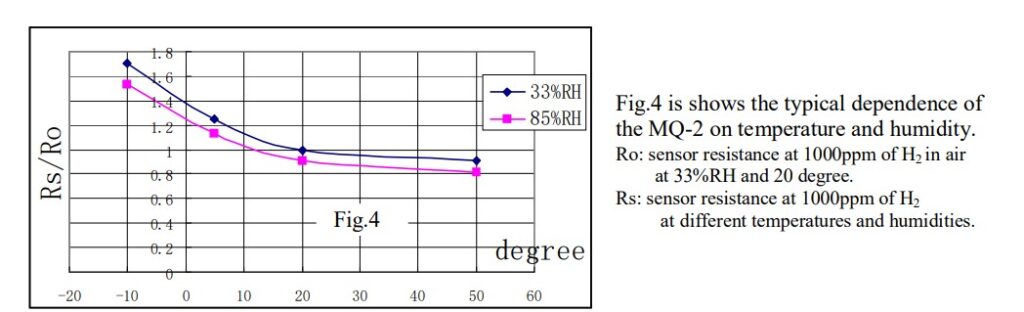
About MQ-2 Sensor:
What gases it detects:
The MQ-2 gas sensor is a low-cost and easy-to-use sensor that can detect a variety of gases commonly found in homes and workplaces. It is widely used for home safety and DIY IoT projects.
What Gases the MQ-2 Sensor Can Detect:
LPG (Liquefied Petroleum Gas) – commonly used for cooking
Methane (CH₄) – found in natural gas and biogas
Butane (C₄H₁₀) – another fuel gas often found in lighters
Smoke – from combustion or fire sources
Hydrogen (H₂) – produced in some industrial processes
Alcohol vapors – volatile organic compounds
Propane (C₃H₈) – used in some household fuel systems
⚠️ Note: The MQ-2 sensor detects the presence of combustible gases like LPG, methane, smoke, and alcohol vapors, but it cannot tell which gas it is. It only gives a voltage output proportional to the overall gas concentration in the air. Perfect for DIY projects and experimentation, but not for precise gas identification.
Hardware Requirements:
o build this project, you will need the following components:
Component
Purpose
ESP32 Development Board
Acts as the main controller and connects to AWS IoT Core
MQ-2 Gas Sensor Module
Detects gases like LPG, methane, and smoke
Relay Module
Used to control appliances remotely via AWS IoT
Jumper Wires
For making connections between ESP32, sensor, and relay
Power Supply
5V for MQ-2 and relay, 3.3V logic for ESP32
Breadboard (optional)
For easy prototyping without soldering
Circuit Connections:
MQ-2 Gas Sensor → ESP32
📌 Safety Note for MQ‑2 Gas Sensor
In many hobby projects, the MQ‑2 gas sensor is connected directly to the ESP32 analog input pin for simplicity. While this works in many cases, it is not technically safe long-term because the MQ‑2 outputs up to 5V analog signals, and ESP32 ADC pins are designed for maximum 3.3V input. Direct connection can lead to:
Gradual damage to ESP32 input pins.
Inaccurate sensor readings.
Reduced reliability over time.
✅ Recommended: Use a simple voltage divider or logic level shifter to scale the MQ‑2 analog output down to safe levels for the ESP32.
VCC → 5V (power for heating element)
GND → GND
A0 → GPIO34 (analog input for reading gas level, use a 5v to 3.3 level shifter)
Relay Module → ESP32 (from previous blog)
VCC → 5V
GND → GND
IN → GPIOXX (same GPIO as used previously for relay control)
Tip: Keep the MQ-2 sensor powered for a few minutes before taking readings to allow it to warm up for accurate measurements.
Firmware Logic:
We take the average of 50 ADC samples from the MQ-2 sensor to ensure stable and reliable readings. This averaged sensor data is then published to AWS IoT Core on the topic:
$aws/things/esp32/sensor/mq2sensor
Alongside this, light control messages are also published to:
$aws/things/esp32/devices/light
For details on how to configure AWS IoT Core and set up publishing and subscribing to topics, please refer to our previous article.
#include <WiFi.h>
#include <WiFiClientSecure.h>
#include <PubSubClient.h>
#include <ArduinoJson.h>

#define MQ2_PIN 34  // ADC pin
#define LIGHT 13

// -------- WiFi ----------
const char* WIFI_SSID = "CHANGE_ME";
const char* WIFI_PASSWORD = "CHANGE_ME";

// -------- AWS IoT ----------
const char* AWS_IOT_ENDPOINT = "CHANGE_ME";  // your AWS IoT Core endpoint
const int AWS_IOT_PORT = 8883;

// Certificates (download from AWS IoT Core)
const char* AWS_CERT_CA = R"EOF(
-----BEGIN CERTIFICATE-----
Replace with your CA content
-----END CERTIFICATE-----
)EOF";

const char* AWS_CERT_CRT = R"EOF(
-----BEGIN CERTIFICATE-----
Replace with your Certificate content
-----END CERTIFICATE-----
)EOF";

const char* AWS_CERT_PRIVATE = R"EOF(
-----BEGIN RSA PRIVATE KEY-----
Replace with your Private Key
-----END RSA PRIVATE KEY-----
)EOF";

// -------- Global Variables ----------
WiFiClientSecure net;
PubSubClient client(net);
int mq2Threshold = 200;

// -------- Functions ----------

// Read MQ2 sensor with averaging
int getMQ2Reading(int samples = 50) {
    long sum = 0;
    for (int i = 0; i < samples; i++) {
        sum += analogRead(MQ2_PIN);
        delay(2);
    }
    return sum / samples;
}

// Handle incoming JSON threshold update
void handleThresholdMessage(char* message) {
    StaticJsonDocument<200> doc;
    DeserializationError error = deserializeJson(doc, message);

    if (error) {
        Serial.print("JSON parse failed: ");
        Serial.println(error.f_str());
        return;
    }

    if (doc.containsKey("threshold")) {
        mq2Threshold = doc["threshold"];
        Serial.print("Threshold updated: ");
        Serial.println(mq2Threshold);
    }
}

// Publish JSON payload to MQTT
void publishMessage(const char* topic, const String& payload) {
    client.publish(topic, payload.c_str());
    Serial.printf("Published [ %s ] %s\n", topic, payload.c_str());
}

// Handle device commands from MQTT
void handle_mqtt_msg(char* topic, byte* payload, unsigned int length) {
    if (strstr(topic, "$aws/things/esp32/devices/light")) {
        if (strstr((const char*)payload, "light-on")) {
            digitalWrite(LIGHT, LOW);
            Serial.println("LIGHT ON");
        } else if (strstr((const char*)payload, "light-off")) {
            digitalWrite(LIGHT, HIGH);
            Serial.println("LIGHT OFF");
        } else {
            Serial.println("LIGHT INVALID COMMAND");
        }
    } else if (strstr(topic, "$aws/things/esp32/sensor/mq2sensor")) {
        handleThresholdMessage((char*)payload);
    }
}

// Prepare sensor data as JSON string
String prepareSensorData(int value) {
    StaticJsonDocument<200> doc;
    doc["value"] = value;
    String payload;
    serializeJson(doc, payload);
    return payload;
}

// MQTT callback
void messageHandler(char* topic, byte* payload, unsigned int length) {
    Serial.print("<< ");
    Serial.print(topic);
    Serial.print(" ");
    for (unsigned int i = 0; i < length; i++) {
        Serial.print((char)payload[i]);
    }
    Serial.println();
    handle_mqtt_msg(topic, payload, length);
}

// Connect to AWS IoT Core
void connectAWS() {
    net.setCACert(AWS_CERT_CA);
    net.setCertificate(AWS_CERT_CRT);
    net.setPrivateKey(AWS_CERT_PRIVATE);

    client.setServer(AWS_IOT_ENDPOINT, AWS_IOT_PORT);
    client.setCallback(messageHandler);
    client.setBufferSize(4096);

    Serial.print("Connecting to AWS IoT Core...");
    while (!client.connected()) {
        client.connect("esp32-gas-sensor");
        Serial.print(".");
        delay(1000);
    }
    client.subscribe("$aws/things/esp32/sensor/mq2sensor");
    Serial.println(" connected!");
}

void setup() {
    Serial.begin(115200);
    pinMode(LIGHT, OUTPUT);

    // Connect to WiFi
    WiFi.begin(WIFI_SSID, WIFI_PASSWORD);
    Serial.print("Connecting to WiFi...");
    while (WiFi.status() != WL_CONNECTED) {
        Serial.print(".");
        delay(1000);
    }
    Serial.println(" connected!");

    // Sensor warm-up
    Serial.println("Warming up sensor...");
    for (int i = 120; i > 0; i--) {
        Serial.printf("Time left: %ds\r", i);
        delay(1000);
    }
    Serial.println("\nSensor is ready!");

    connectAWS();
}

void loop() {
    int sensorValue = getMQ2Reading();
    int mappedValue = map(sensorValue, 0, 4095, 0, 1024);

    static unsigned long lastTime = 0;
    unsigned long currentTime = millis();

    if (currentTime - lastTime > 5000) {  // every 5 seconds
        lastTime = currentTime;
        Serial.printf("MQ2 ADC Reading: %d\n", mappedValue);
        publishMessage("$aws/things/esp32/sensor/mq2sensor", prepareSensorData(mappedValue));
    }

    if (!client.connected()) {
        connectAWS();
    }

    client.loop();
}
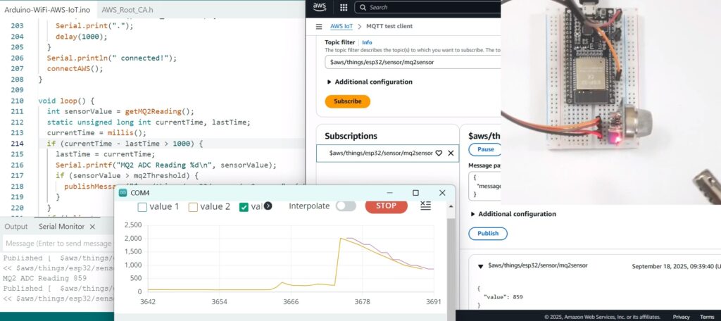
Hands-on Testing with AWS IoT Core Client:
Hardware Setup Connect the MQ-2 sensor as shown in the above circuit diagram.
Upload Firmware Flash the ESP32 firmware after updating your Wi-Fi credentials, AWS endpoint, and certificates.
Monitor Output Open the Serial Monitor or Serial Plotter in Arduino IDE.
In normal conditions, you should see ADC readings in the range of 100–200.
Now bring a gas lighter close to the sensor and press the button. You will notice the ADC readings rise sharply.
Threshold & AWS Publish Once the reading crosses the default threshold, the ESP32 will publish a message to AWS IoT Core. (Refer to the figure below for the AWS IoT Core dashboard output).
👉 For AWS IoT Core certificate and policy setup, please refer to our previous blog. 👉 In the next part, we will cover Android App configuration and implementation for receiving notifications.
In this guide, you’ll learn how to connect an ESP32-WROOM-32 (38 Pin) development board to AWS IoT Core using the MQTT protocol. You’ll also control a 2-Channel Relay Module with optocoupler to switch devices remotely via the cloud. This is a perfect starting point for building smart home systems, industrial IoT projects, or remote device management solutions.
By the end of this tutorial, you will:
Set up AWS IoT Core for secure device communication.
Program the ESP32 to communicate via MQTT.
Control relays connected to the ESP32 from AWS.
Prerequisites
Before you get started with AWS IoT Core and ESP32, make sure you have the following:
Creating and Configuring a Thing in AWS IoT Core:
Basic Knowledge of MQTT Protocol Understanding of MQTT topics, publish/subscribe model, and message handling.
ESP32-WROOM-32 (38 Pin) Development Board A compatible ESP32 board for connecting to AWS IoT Core.
2-Channel Relay Module with Optocoupler To control external devices or appliances via the ESP32.
Active AWS Account Necessary for creating IoT Things, certificates, and policies on AWS IoT Core.
Latest Arduino IDE Installed Required for writing, compiling, and uploading code to the ESP32 board.
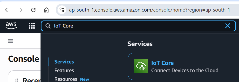
Start by logging into your AWS Management Console with the root user credentials. This guide assumes that your AWS account has already been created.
✅ If you’re a new user and need help setting up an AWS account from scratch, we’ll cover that in a detailed article soon. 🎥 Meanwhile, follow this video to quickly create your AWS account step by step!
Search for IoT Core:
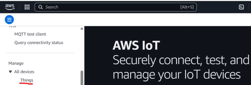
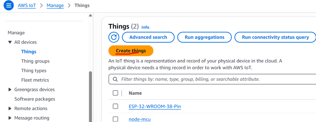
Select AWS IoT Core and Click on Things:
Click on create things:
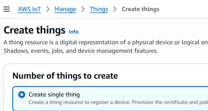
Click on create single thing:
Understanding AWS IoT Shadows: No Shadow, Named Shadow, and Unnamed (Classic) Shadow
When you create a Thing in AWS IoT Core, you can choose how its state (shadow) will be managed. Device Shadows allow AWS IoT Core to store the device’s last reported and desired states, even when the device is offline. Here’s a quick overview of the available options:
1. No Shadow
If you select this option, AWS IoT Core will not maintain any shadow document for the device. The device must handle state management entirely through direct communication (such as MQTT messages). This is suitable for devices that do not require state persistence.
2. Unnamed (Classic) Shadow
Also known as the default shadow, the unnamed or classic shadow provides a single JSON document that represents the entire device state. This is ideal for simpler devices where one shadow is enough to reflect the device’s status, commands, and configuration.
3. Named Shadow
Named shadows allow you to create multiple shadow documents for the same Thing. This is useful for complex devices with multiple components — for example, a smart home device that manages both a thermostat and a light system can have separate named shadows for each component.
For This Tutorial: Selecting ‘No Shadow’ for Simplicity
In this guide, we will choose the ‘No Shadow’ option to keep the setup simple. This means AWS IoT Core will not maintain a Device Shadow for our Thing, and all device state management will rely on direct communication (such as MQTT messages). This approach is suitable for basic use cases or when shadow functionality is not required.
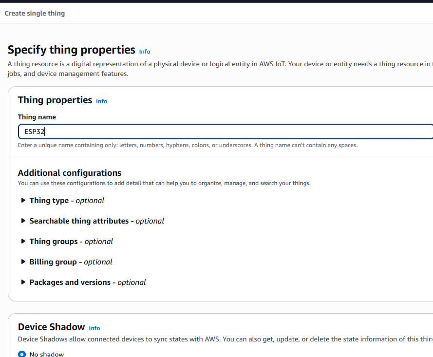
Assigning a Thing Name and Keeping Default Settings
For this example, set the Thing Name as “ESP32” to represent your IoT device. Leave all other settings at their default values to simplify the configuration process. This ensures a quick and hassle-free setup, especially suitable for beginners or testing purposes.
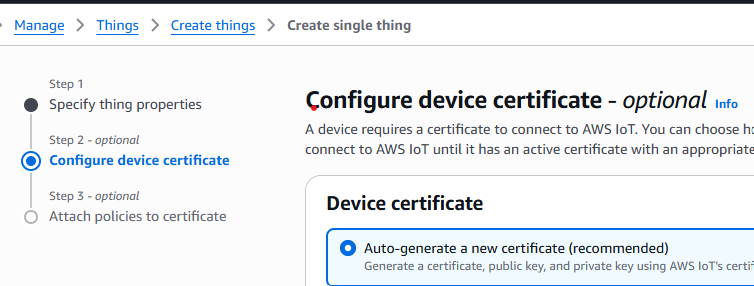
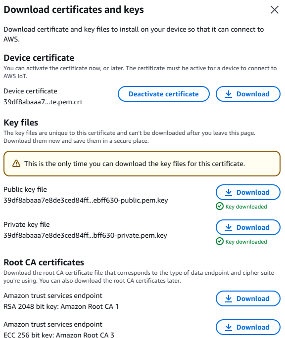
Generate Certificates with Default Settings
In the next step, choose the option to automatically generate a new certificate and keep all other settings at their default values. AWS IoT Core will create a certificate and private key pair for your Thing, which is essential for secure device authentication and communication.
After the certificates are generated, be sure to download them for future use, as they won’t be accessible later.
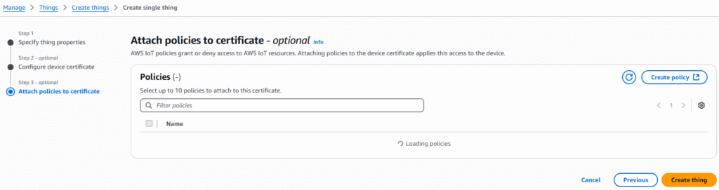
Skip Policy Attachment for Now and Create the Thing
For this tutorial, we will not attach any policy at this stage. Policies define permissions for your device, but we will create and attach a policy separately in a later step.
Simply click on “Create Thing” to complete the process. Your AWS IoT Thing (named ESP32) will now be created with default settings and a generated certificate.
Download All Certificates for Future Use
Once the Thing is created, make sure to download all the generated certificates and the private key file. These files are essential for establishing a secure connection between your ESP32 device and AWS IoT Core. Without these certificates, the ESP32 will not be able to authenticate and communicate with AWS IoT services.
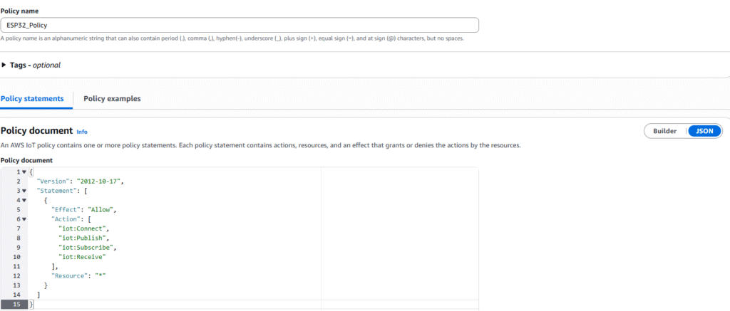
Creating an AWS IoT Policy for ESP32
When creating the policy, use the following JSON policy document. This policy grants the required permissions to your ESP32 device for connecting, publishing, subscribing, and receiving messages in AWS IoT Core:
In left side panel go to Security->Policies->Create Policy and select JSON
⚠️ Important: This policy provides full access to AWS IoT Core resources ("Resource": "*"). For production environments, it’s recommended to restrict this to specific IoT Things or topics to ensure better security.
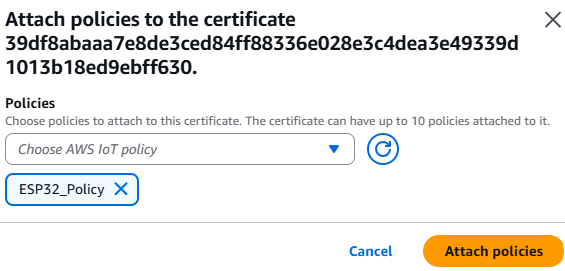
Attach the Policy to the Thing’s Certificate
Now that the IoT Policy has been created, the next step is to attach it to the certificate associated with your ESP32 Thing. This allows your device to securely communicate with AWS IoT Core using the permissions defined in the policy.
Steps to Attach the Policy:
Go to the AWS IoT Core Console.
In the left sidebar, navigate to Security → Certificates.
Find the certificate you created earlier (associated with the ESP32 Thing).
Click on the certificate ID to open its details.
Under “Actions”, click “Attach policy”.
From the list, select the policy you just created (e.g., ESP32_Policy) and click “Attach”.
✅ Now your ESP32 certificate is authorized to connect and interact with AWS IoT Core.
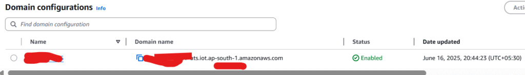
Note Down the Device Endpoint
Carefully note down the AWS IoT Device Endpoint URL, as this will be required later when configuring your ESP32 to securely connect to AWS IoT Core.
You can find this endpoint in the AWS IoT Core Console under AWS Console → Connect -> Domain Configurations
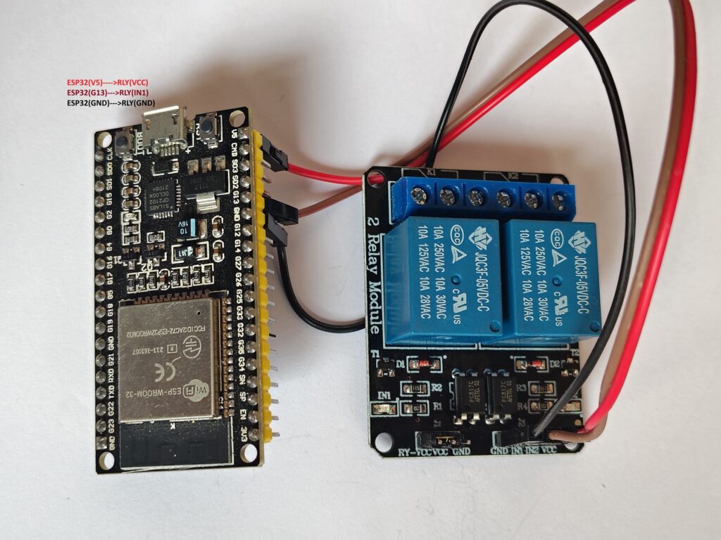
🔌 Connecting 5V Relay Module to ESP32 (Using GPIO13)
ESP32 Pin
Relay Module Pin
Function
V5 (5V)
VCC
Power supply for the relay module
GPIO13 (G13)
IN1
Relay control input
GND
GND
Common ground connection
Steps to Connect ESP32 to AWS IoT Core
const char WIFI_SSID[] = “Change This”;
const char WIFI_PASSWORD[] = “Change This”;
const char AWS_IOT_ENDPOINT[] = “Use this from previous step”; //change this
Upload the ESP32 Sketch After Updating Required Details
Use the following ESP32 Arduino sketch to connect your device to AWS IoT Core. Before uploading, make sure to update the placeholders with your specific AWS IoT credentials:
Wi-Fi SSID and Password
AWS IoT Endpoint URL
Root CA Certificate
Device Certificate
Private Key
⚠️ Important: Replace the placeholder values with the actual credentials and endpoint you obtained from AWS IoT Core.
#include <WiFi.h>
#include <WiFiClientSecure.h>
#include <PubSubClient.h>
// -------- WiFi ----------
const char* WIFI_SSID = "CHANGE_ME";
const char* WIFI_PASSWORD = "CHANGE_ME";

// -------- AWS IoT ----------
 /*This is the unique DNS address given by AWS IoT Core,
 which acts as the MQTT broker for your device to communicate with cloud services.*/
const char* AWS_IOT_ENDPOINT = "change-me";
/*This is the port used for the MQTT protocol, typically 8883 for secure (TLS) communication.*/
const int AWS_IOT_PORT = 8883;

// Certificates (download from AWS IoT Core)
const char* AWS_CERT_CA = R"EOF(
-----BEGIN CERTIFICATE-----
UPDATE ME
-----END CERTIFICATE-----
)EOF";

const char* AWS_CERT_CRT = R"EOF(
-----BEGIN CERTIFICATE-----
UPDATE ME
-----END CERTIFICATE-----
)EOF";

const char* AWS_CERT_PRIVATE = R"EOF(
-----BEGIN RSA PRIVATE KEY-----
UPDATE ME
-----END RSA PRIVATE KEY-----
)EOF";
#define LIGHT 13
// -------- Global Variables ----------
WiFiClientSecure net;
PubSubClient client(net);

void publishMessage(const char* topic, char* payload) {
  client.publish(topic, payload);
  Serial.print("Published [ ");
  Serial.print(" ");
  Serial.print(topic);
  Serial.print("] ");
  Serial.println(payload);
}

// Connect to AWS IoT Core
void connectAWS() {
    /*This loads the root CA certificate provided by AWS (Amazon Root CA),
    which is used to verify that the AWS server the IoT device connects
    to is legitimate.*/
    net.setCACert(AWS_CERT_CA);
    /*It is used by the AWS server to verify the identity of your specific
    IoT device when it tries to connect.*/
    net.setCertificate(AWS_CERT_CRT);
    /*The private key ensures that only your device can prove ownership of its
    certificate, supporting secure encrypted communication.*/
    net.setPrivateKey(AWS_CERT_PRIVATE);

    client.setServer(AWS_IOT_ENDPOINT, AWS_IOT_PORT);
    client.setCallback(messageHandler);
    Serial.print("Connecting to AWS IoT Core...");
    while (!client.connected()) {
        client.connect("ESP32");
        Serial.print(".");
        delay(1000);
    }
    client.subscribe("$aws/things/ESP32/command/light");
    Serial.println(" connected!");
}

void handle_mqtt_msg(char *topic, byte *payload, unsigned int length) {
  char resp[60] = { 0 };
  if (strstr(topic, "$aws/things/ESP32/command/light")) {
    if (strstr((const char *)payload, "light-on") != NULL) {
      digitalWrite(LIGHT, LOW);
      Serial.println("relay_update(LIGHT,LOW)");
    } else if (strstr((const char *)payload, "light-off") != NULL) {
      digitalWrite(LIGHT, HIGH);
      Serial.println("relay_update(LIGHT,HIGH)");
    } else {
      Serial.println("relay_update(LIGHT,INVALID)");
    }
  } else {
    Serial.println("Invalid: command");
  }
}

void messageHandler(char *topic, byte *payload, unsigned int length) {
  Serial.print("Message arrived [");
  Serial.print(topic);
  Serial.print("] ");
  for (int i = 0; i < length; i++) {
    Serial.print((char)payload[i]);
  }
  handle_mqtt_msg(topic, payload, length);
  Serial.println();
}

void setup() {
    pinMode(LIGHT, OUTPUT);
    digitalWrite(LIGHT, HIGH);
    Serial.begin(115200);
       // Connect to WiFi
    WiFi.begin(WIFI_SSID, WIFI_PASSWORD);
    Serial.print("Connecting to WiFi...");
    while (WiFi.status() != WL_CONNECTED) {
        Serial.print(".");
        delay(1000);
    }
    Serial.println(" connected!");
    connectAWS();
}

void loop() {
    static unsigned long lastTime = 0;
    unsigned long currentTime = millis();

    if (currentTime - lastTime > 5000) {  // every 5 seconds
        lastTime = currentTime;
        String message = "Hello from ESP32";
        String jsonPayload = "{\"message\": \"" + message + "\"}";
        publishMessage("$aws/things/esp32/data", (char *)jsonPayload.c_str());
    }

    if (!client.connected()) {
        connectAWS();
    }

    client.loop();
}
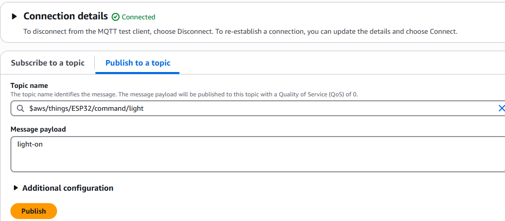
AWS IoT Topic and Message Structure for Relay Control
MQTT Topic
Message Payload
Action Performed
$aws/things/ESP32/command/light
light-on
Turns the relay (light) ON
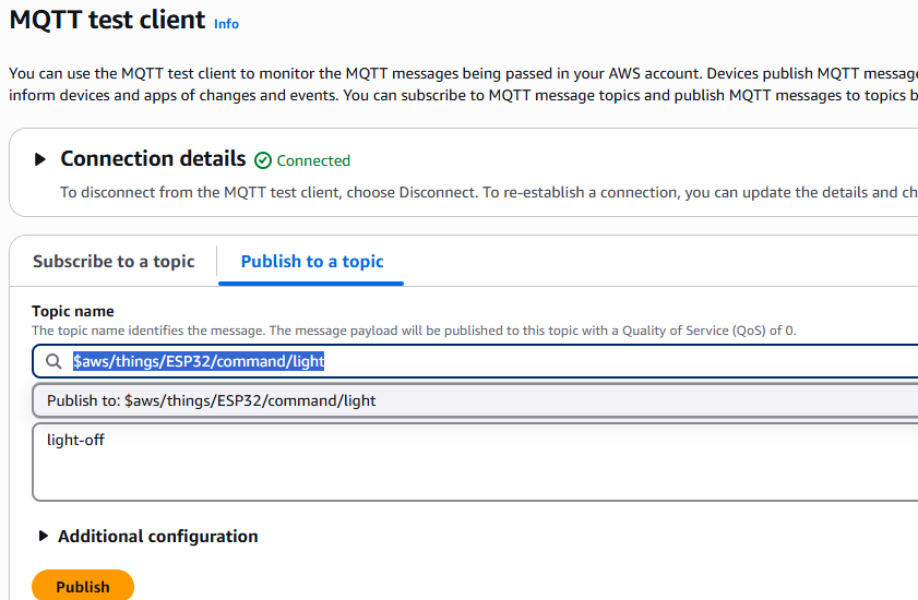
$aws/things/ESP32/command/light
light-off
Turns the relay (light) OFF
To turn on the relay, send below command and message
To turn off the relay send below command and message
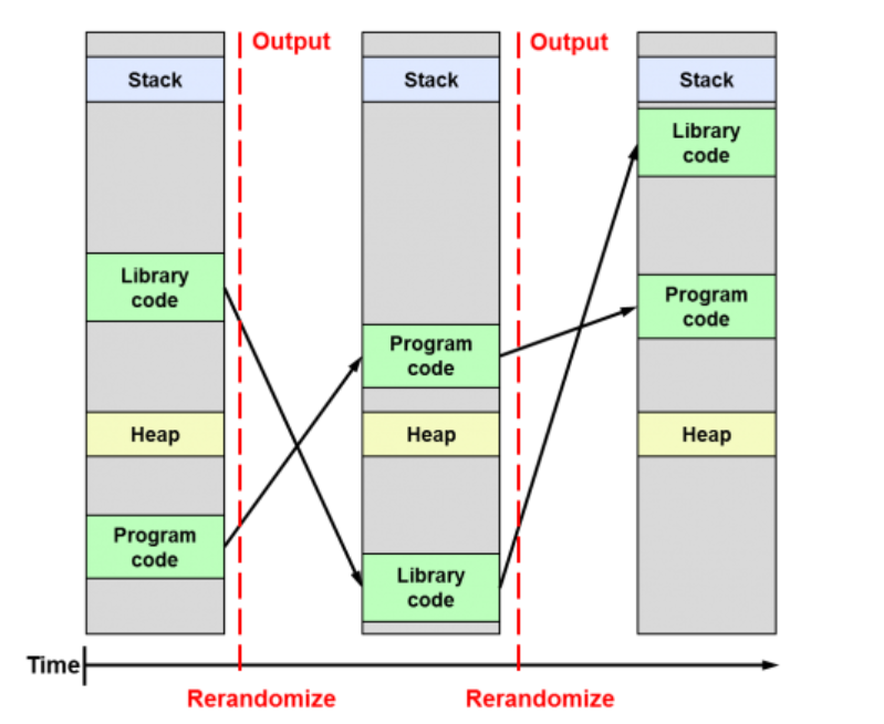
ASLR (Address Space Layout Randomization) is a security technique used to prevent exploitation of memory corruption vulnerabilities, such as buffer overflow attacks. It works by randomly arranging the memory address space of a process each time it runs, making it harder for attackers to predict the location of specific functions, buffers, or data within the memory.
By randomizing the locations of these elements, ASLR makes it more difficult for malicious code to exploit vulnerabilities, as the attacker can’t rely on fixed memory addresses. This adds an extra layer of defense against certain types of cyberattacks.
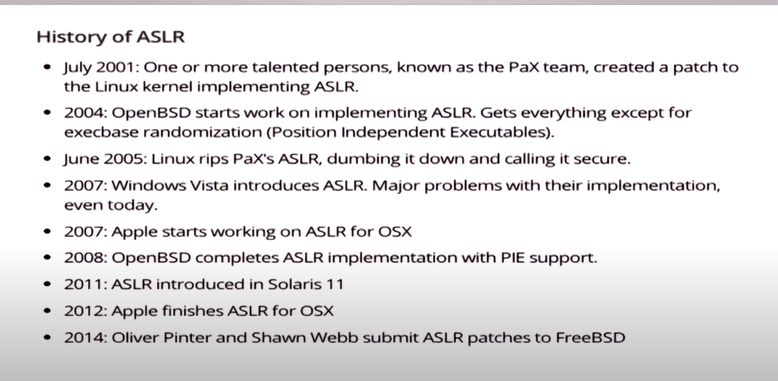
When and How It Was First Implemented
ASLR (Address Space Layout Randomization) was first introduced in 2001 by Solar Designer, a security researcher, as part of the PaX project (which aimed to provide additional security features for Linux systems). It was later integrated into the Linux kernel and other operating systems over time.
In 2003, ASLR was added to OpenBSD, which was one of the first operating systems to fully implement it. After that, other major operating systems, such as Windows and macOS, started adopting ASLR as a default security measure in the following years.
So, it has been around for quite a while and is now considered a standard security feature in most modern operating systems!
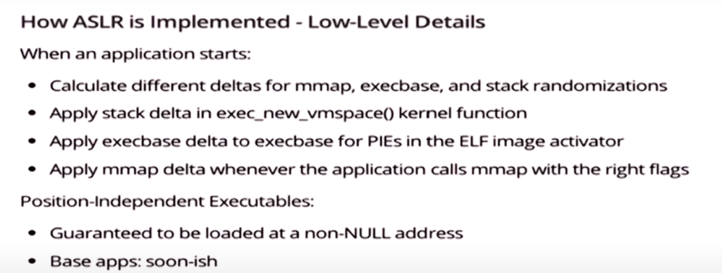
How to Enable ASLR on FreeBSD
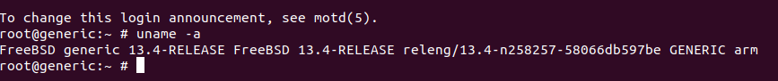
Support for Address Space Layout Randomization was added in FreeBSD HEAD (13-CURRENT) in base r343964. It is enabled by default in 14-CURRENT for 64bit architectures, as of base commit b014e0f15bc7. It is enabled by default for 64-bit architectures in FreeBSD 13.2 and later releases.
ASLR is enabled on a per-ABI basis, and is supported on all architectures as of 72091bb39382abba0d71dc23738684bfb4bc2574.
kern.elf{32,64}.aslr.enable – Enable address map randomization (Default: 1 for 64bit architectures, 0 for 32bit architectures)
kern.elf{32,64}.aslr.pie_enable – Enable ASLR for Position-Independent Executables (PIE) binaries (Default: 1 for 64bit architectures, 0 for 32bit architectures)
kern.elf{32,64}.aslr.honor_sbrk – Assume sbrk is used (Default: 0)
ASLR introduces additional computation to randomize memory addresses. This can cause a small but noticeable performance overhead, particularly in programs that make frequent use of system calls or deal with memory addresses regularly. While the performance hit may not be significant for most applications, it can become more noticeable in high-performance or latency-sensitive environments.
Tests on the tier 1 64-bit architectures demonstrated that the ASLR is stable and does not result in noticeable performance degradation, therefore it should be safe to enable this mechanism by default. Moreover its effectiveness is increased for PIE (Position Independent Executable) binaries. Thanks to commit 9a227a2fd642 (“Enable PIE by default on 64-bit architectures”), building from src is not necessary to have PIE binaries. It is enough to control usage of ASLR in the OS solely by setting the appropriate sysctls.
As for the drawbacks, a consequence of using the ASLR is more significant VM fragmentation, hence the issues may be encountered in the systems with a limited address space in high memory consumption cases, such as buildworld. As a result, although the tests on 32-bit architectures with ASLR enabled were mostly on par with what was observed on 64-bit ones, the defaults for the former are not changed at this time. Also, for the sake of safety keep the feature disabled for 32-bit executables on 64-bit machines, too.
Compatibility Issues with Legacy Software:
Some older or legacy applications may not be designed to work with ASLR and may exhibit instability or unexpected behavior. This is because ASLR changes memory locations, and older software might assume fixed addresses, leading to crashes or failures. Debuggers and other tools that rely on knowing the memory layout might also struggle to work properly with ASLR-enabled systems.
Increased Complexity in Exploit Development:
While ASLR is a defense against certain types of exploits (like buffer overflows), it can increase the complexity of attacks that rely on knowing the memory addresses of particular functions or variables. This, however, is more of an advantage in terms of security than a disadvantage, but it can also lead to more sophisticated attacks that might bypass ASLR (e.g., using information leaks or other techniques).
Increased Attack Surface (Side-channel Attacks):
In some scenarios, ASLR can make certain types of side-channel attacks (such as those based on timing or memory access patterns) more feasible, especially if other security measures are not in place. Attackers may use techniques like cache timing attacks to defeat ASLR.
Limited Protection for Some Types of Vulnerabilities:
While ASLR protects against certain kinds of buffer overflow and memory corruption attacks, it does not address other vulnerabilities, such as those in the application logic or in protocols (e.g., SQL injection, XSS). As a result, relying solely on ASLR for security is insufficient.
Randomization Limitations:
In FreeBSD, ASLR randomness may not be as robust or fine-grained as in other systems like Linux. The lack of highly unpredictable entropy sources or the potential for weaker randomization could reduce the effectiveness of ASLR as a security measure.
Setting up FreeBSD on BeagleBone Black can be straightforward. However, you need to follow the correct steps. In addition, the process requires some basic knowledge of FreeBSD and BeagleBone.
Prerequisites for Installing FreeBSD on Beaglebone Black
Beaglebone black.
5v power supply or Mini-USB cable.
Micro-SDHC card 16GB or larger.
USB to Serial (TTL) Converter.
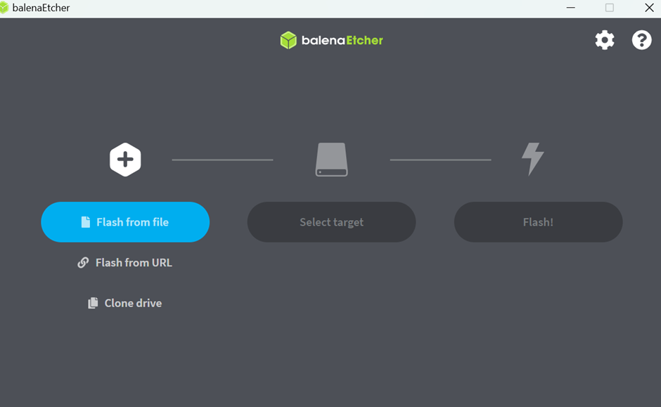
BalenaEtcher installed on windows Or Ubuntu 20.04.6 LTS or Latest
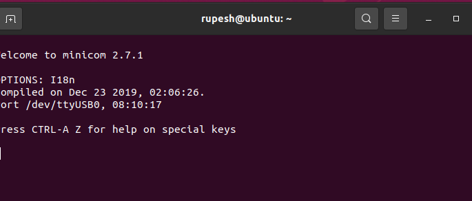
Open minicom on ubuntu or teraterm on windows. For windows you might have to search for usb to ttl drivers, we are using minicom on ubuntu to avoid that
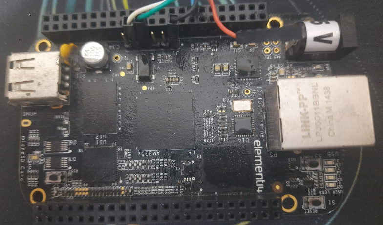
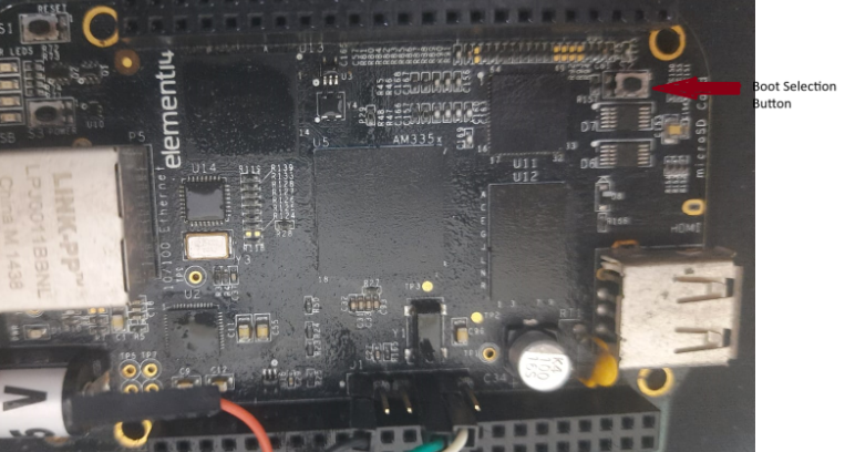
Press and hold boot button on Beaglebone Black and plugin the power source
In this article, we will guide you through setting up your own VPN. If you have a public IP, you can set it up on a BeagleBone Black. Alternatively, if you don’t have a public IP, you can deploy the VPN on an AWS t4g.micro instance. For AWS deployments, it’s recommended to use an Elastic IP to prevent IP changes when the instance is stopped. We will cover the AWS instance deployment process separately.
Setup server on Beaglebone black
Please make sure you have listed items ready
Beaglebone black.
5v power supply or Mini-USB cable.
Micro-SDHC card 16GB or larger.
Serial cable such as Adafruit #954 or FTDI TTL232R-3V3 (optional but highly recommended).
BalenaEtcher installed on windows
Install FreeBSD 13.4 Image on BeagleBone Black
Download FreeBSD-13.4-RELEASE-arm-armv7-GENERICSD.img from freebsd website.
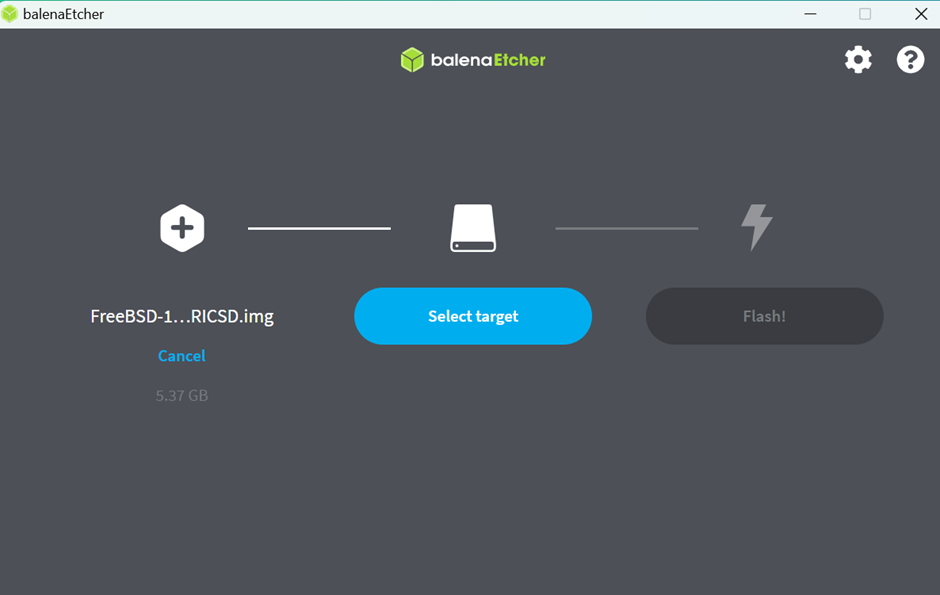
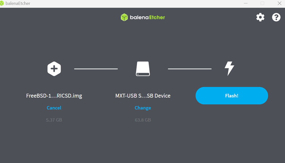
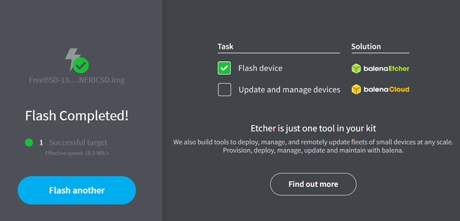
Use BalenaEtcher to write the image to SD card
Insert SD card and boot from SD card. Here I am assuming user knows how to boot new image from SD card and get ssh working. Please follow this link to Flash Image on SD card https://vihaaniotgateway.in/index.php/2025/01/19/setting-up-freebsd-on-beaglebone-black-an-easy-installation-guide/
Connect Beaglebone black to LAN and login through ssh
Setup OpenVPn server on Beaglebone black/AWS t4g.micro instance
Install OpenVPN on Your Server
Configure OpenVPN Server Settings
Set Up PKI and Configure Environment Variables for EasyRSA
Generate Server Certificates for Secure Connection
We are using tcp port 80 because it would be easy to migrate to AWS. There is only one (external n/w interface)difference between aws and beagle bone black. All steps would be same except pf rules and instance deployement,
cat oprnvpn.conf.patch --- /usr/local/etc/openvpn/openvpn.conf.orig 2024-12-22 14:10:58.899905000 +0000 +++ /usr/local/etc/openvpn/openvpn.conf 2024-12-22 14:40:56.878042000 +0000 @@ -29,11 +29,12 @@ # on the same machine, use a different port # number for each one. You will need to # open up this port on your firewall. -port 1194 +;port 1194 +port 80
# "dev tun" will create a routed IP tunnel, # "dev tap" will create an ethernet tunnel. @@ -83,14 +84,18 @@ dev tun # and use the peer-fingerprint option. # See openvpn-examples man page for a # configuration example. -ca ca.crt -cert server.crt -key server.key # This file should be kept secret +;ca ca.crt +;cert server.crt +;key server.key # This file should be kept secret +ca /usr/local/etc/openvpn/keys/ca.crt +cert /usr/local/etc/openvpn/keys/openvpn-server.crt +key /usr/local/etc/openvpn/keys/openvpn-server.key +dh /usr/local/etc/openvpn/keys/dh.pem
# Diffie hellman parameters. # Generate your own with: # openssl dhparam -out dh2048.pem 2048 -dh dh2048.pem +;dh dh2048.pem
# Allow to connect to really old OpenVPN versions # without AEAD support (OpenVPN 2.3.x or older) @@ -112,7 +117,8 @@ topology subnet # Each client will be able to reach the server # on 10.8.0.1. Comment this line out if you are # ethernet bridging. See the man page for more info. -server 10.8.0.0 255.255.255.0 +;server 10.8.0.0 255.255.255.0 +server 172.16.100.0 255.255.255.0
# Maintain a record of client <-> virtual IP address # associations in this file. If OpenVPN goes down or @@ -220,7 +226,7 @@ ifconfig-pool-persist ipp.txt # To force clients to only see the server, you # will also need to appropriately firewall the # server's TUN/TAP interface. -;client-to-client +client-to-client
# Uncomment this directive if multiple clients # might connect with the same certificate/key @@ -233,7 +239,7 @@ ifconfig-pool-persist ipp.txt # CERTIFICATE/KEY PAIRS FOR EACH CLIENT, # EACH HAVING ITS OWN UNIQUE "COMMON NAME", # UNCOMMENT THIS LINE. -;duplicate-cn +duplicate-cn
# The keepalive directive causes ping-like # messages to be sent back and forth over @@ -268,7 +274,8 @@ keepalive 10 120 # systems after creating a dedicated user. ;user openvpn ;group openvpn - +user nobody +group nobody # The persist options will try to avoid # accessing certain resources on restart # that may no longer be accessible because @@ -307,4 +314,4 @@ verb 3
# Notify the client that when the server restarts so it # can automatically reconnect. -explicit-exit-notify 1 \ No newline at end of file +explicit-exit-notify 1
Enable IP Forwarding for Network Traffic Routing
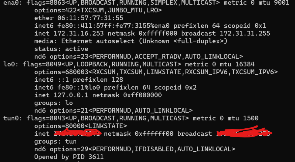
This is needed if you want your internet traffic route through vpn tunnel, otherwise vpn connected devices won’t be able to reach to internet. I am not sure if there is a better way to do this, I was able to make it work by using this approach. Once openvpn is up then you should see tun0 interface up. The screenshot is taken from aws t4g.micro instance. On Beaglebone black also it would look similar except it will display cpsw0 instead of ena0 for externel interface.
service openvpn status openvpn is running as pid 804.
echo 'pf_load="YES"' >> /boot/loader.conf
echo 'net.inet.ip.forwarding=1' >> /etc/sysctl.conf
**********For AWS Instance Only**************************
echo 'nat on ena0 from 172.16.100.0/24 to any -> (ena0)' > /etc/pf.conf
**************For BeagleBone Black Only*******************
echo 'nat on cpsw0 from 172.16.100.0/24 to any -> (cpsw0)' > /etc/pf.conf
sysrc pf_enable="YES"
sysrc gateway_enable="YES"
reboot
Create Client Certificates for VPN Access
cd /usr/local/etc/openvpn/easy-rsa;
easyrsa build-client-full openvpn-aws-client nopass;
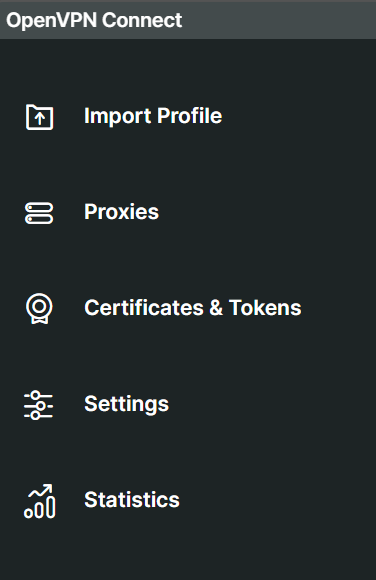
Connect Client On Windows 11
Install OpenVpn Connect For Windows
Create .ovpn file and write this data
client
dev tun
proto tcp
remote aws/beaglebone-black-public-ip 80
persist-key
persist-tun
redirect-gateway def1
<ca>
-----BEGIN CERTIFICATE-----
Replace with the ca data  cat /usr/local/etc/openvpn/keys/ca.crt
-----END CERTIFICATE-----
</ca>
<cert>
-----BEGIN CERTIFICATE-----
Replace with cert cat /usr/local/etc/openvpn/easy-rsa/pki/issued/openvpn-aws-client.crt
-----END CERTIFICATE-----
</cert>
<key>
Replace with client key cat /usr/local/etc/openvpn/easy-rsa/pki/private/openvpn-aws-client.key
</key>
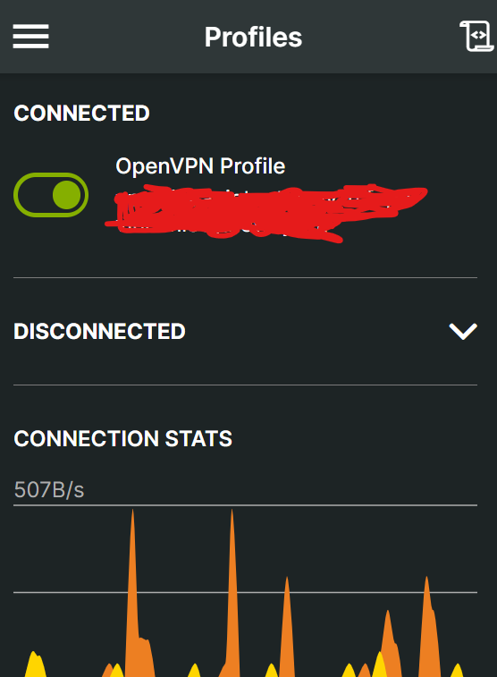
Import Profile in OpenVpn Connect App
Install OpenVpn Connect For Windows
Import above created .ovpn file
Click on connect, you should be able to connect to vpn
Steps to deploy aws t4g.micro instance To be continued …
Issues faced and References:
Initially I struggled to make internet work on vpn connected devices and found that only pf configuration and ip forwarding made it work. I added this in Beaglebone black configuration openvpn.conf but looks like it is not required as today I configured without this on aws without these changes.
# To assign specific IP addresses to specific @@ -204,6 +208,7 @@ ifconfig-pool-persist ipp.txt # or bridge the TUN/TAP interface to the internet # in order for this to work properly). ;push “redirect-gateway def1 bypass-dhcp” +push “redirect-gateway def1”
# Certain Windows-specific network settings # can be pushed to clients, such as DNS @@ -213,6 +218,8 @@ ifconfig-pool-persist ipp.txt # DNS servers provided by opendns.com. ;push “dhcp-option DNS 208.67.222.222” ;push “dhcp-option DNS 208.67.220.220” +push “dhcp-option DNS 8.8.8.8” +push “dhcp-option DNS 8.8.4.4”